
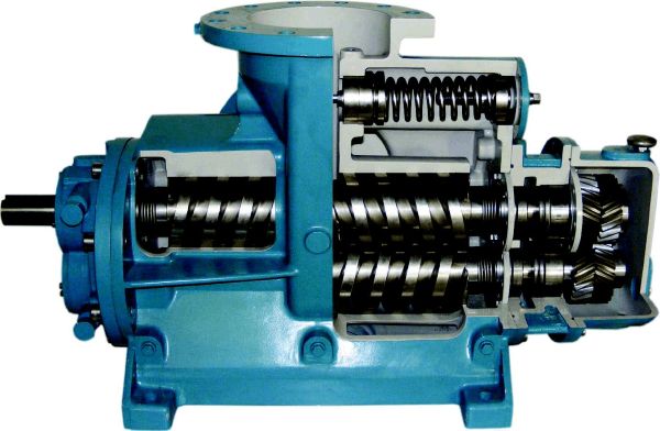
Twin-screw pumps are widely used on ships. They are characterized by stable liquid delivery, low vibration, low noise, strong self-priming capability, a wide range of media to be transported, and a long service life. They are mainly used for the transfer of fuel oil, lubricating oil, and various chemicals.
Because light fuel oil and chemicals are flammable and explosive and pose a strong hazard to human health, twin-screw pumps must be leak-free during operation. Twin-screw pumps have high requirements for bearing temperature during operation; generally, the bearing temperature after repair should not exceed 70℃.
This article, from the perspective of ship repair, outlines the repair procedures for twin-screw pumps during maintenance, hoping to provide some reference for marine engineering managers.
I. Preparatory Work Before Twin-Screw Pump Repair
Preparatory work before repair is very important. First, carefully read the twin-screw pump instruction manual and related parameters. Based on the usage and maintenance records of the twin-screw pump, if conditions permit, the pump should be started and run for inspection before disassembly to visually understand the pump’s problems and malfunctions. After understanding the basic operating status and faults of the pump to be repaired, a corresponding repair plan should be formulated, and a suitable repair site should be selected. A safety assessment should be conducted for the repair, and appropriate repair tools should be selected.
II. Disassembly of the Pump and Accessories
First, disassemble the pump and its auxiliary piping system. The pump inlet and outlet pipes should be sealed promptly to prevent oil and gas leakage from the pipeline, while ensuring ventilation. If the pump is used to transport chemicals, ensure that you do not touch the liquid flowing out of the pipes during disassembly to avoid injury. If you accidentally touch it, wash it with water immediately. Carefully inspect the disassembled coupling nylon rods. If the wear is minor, keep them for continued use; otherwise, replace them. If the nylon rods are found to be severely worn, it indicates that the centerline of the twin-screw pump is inaccurate; pay attention to adjusting the centerline during installation. After disassembling the pump, mark the gaskets on all mounting feet and store them properly for use during installation and alignment, or make new gaskets according to the thickness of each gasket.
III. Workshop Disassembly and Repair
After the disassembled twin-screw pump is transported to the workshop, disassembly and inspection begin. If the pump is used for chemical transport, it needs to be rinsed with water before disassembly to remove any residual chemicals.
1. Marking
Before disassembly, make clear marks. Mark the end covers, gears, bearing housings, drive shaft, and driven shaft to avoid incorrect reassembly. Pay special attention if the screw has a double thread; mark the relative position on the shaft, otherwise it may be rotated 180° during reassembly.
2. Disassembly
After marking the positions, disassemble the twin-screw pump sequentially according to the instructions. Drain the fuel (lubricating) oil from the gearbox, remove the gearbox cover, loosen the gear lock nut, and remove the gear; inspect the gear for wear.
Generally, the gears should be fine.
The safety shim of the lock nut needs to be replaced during installation. After removing the gear, the gear end cover along with the bearing can be pulled out. This bearing is a single-row roller bearing with axially free movement of the inner ring. Due to its high radial load capacity, it is mainly used to bear the radial load of the shaft. The fit between the inner and outer rings of the bearing and the journal and bearing housing bore is relatively loose, making disassembly and assembly easy. There are usually adjusting shims between the bearing and the gear. Mark the adjusting shims and keep them safe for future installation. These shims are mainly used to adjust the screw clearance because the drive gear is helical.
Remove the input end bearing cover, remove the bearing lock nut, and use a lead screw to push out the input end cover along with the bearing.
The bearing’s inner and outer rings are interference-fitted with the journal and bearing housing bore. If it cannot be removed using a lead screw, the bearing can be removed by breaking it, but care must be taken to ensure that the shaft and bearing housing bore are not damaged.
When removing the end covers, install guide rods to prevent damage to the shaft seal.
After removing the end covers from both ends of the pump, the mechanical seal’s rotating ring on the pump shaft and the mechanical seal’s stationary ring fixed to the shaft seal seat on the pump end cover can be seen.
The entire pump’s sealing relies on these four sets of mechanical seals at both ends of the two pump shafts. Therefore, these four sets of mechanical seals must be installed with extreme care, as the stationary rings of the mechanical seals are mostly made of carbon fiber, which is very brittle and easily damaged.
Finally, lift the two pump shafts out of the pump body. Remove the bearings from the pump end covers and remove the shaft seal seats.
3. Cleaning, Inspection, and Repair
After removing the pump shafts, first check the wear condition of the pump housing bore and the screw, and measure the clearance between the pump housing bore and the screw.
If the wear is severe and the clearance exceeds the standard, since there is currently no feasible repair plan or repair value, the entire unit must be replaced.
If the wear of the pump shaft and pump casing is within specifications, proceed with the following repairs:
Clean and inspect the pump shaft seal and bearing positions for corrosion and wear. If the bearing inner ring is worn, or if the shaft seal is corroded and affecting the seal, it should be chrome-plated for repair.
The chrome plating layer must have a certain thickness; otherwise, the plating will easily peel off. Measure the runout of the pump shaft on a lathe.
This work is crucial. Excessive runout of the pump shaft and screw will lead to significant vibration and noise during pump operation, accelerating wear; it will also cause excessively high bearing temperatures during use, a direct cause of accelerated wear, poor shaft seal sealing, and shortened shaft seal life.
Therefore, this work must be performed during repairs regardless of the pump’s condition. Once excessive runout is detected, it must be repaired; this is one of the key points affecting the overall repair quality and service life of the pump.
Check the pump shaft screw locking nut for looseness. If loose, loosen and retighten it. If the nut is rusted, replace it. If the pump shaft threads are corroded, repair the pump shaft. After loosening the nut, check for looseness between the screw and the pump shaft. If the gap is large, remove the screw and inspect the wear and corrosion of the screw inner hole and keyway. Repair the screw inner hole and pump shaft as needed, or replace them.
If replacement is necessary, it is best to replace both pump shafts as a set. Replacing only a screw or a pump shaft will reduce the screw’s meshing accuracy. Clean, inspect, and measure the bearing housing bore. If wear is found, send it for external iron plating repair. Remove the shaft seal seat, clean and inspect it for corrosion and wear. Repair as needed to ensure sealing.
IV. Workshop Assembly
1. Mechanical Seal Inspection
New mechanical seals must use original factory parts. Carefully inspect the appearance and sealing surface.
First, compare the seal with the old one to ensure the size and height are the same, and check if it fits properly on the shaft and seat. Then, perform a visual inspection, checking for any defects on the seal surface, the smoothness of the sealing surface, and whether the spring and spring seat material meet the requirements (it must be stainless steel; rust will cause the spring to seize and the seal to fail), ensuring it is not a refurbished part.
There are two common inspection methods.
One is to place the stationary ring with its sealing surface facing up on a flat surface, then place the rotating ring with its sealing surface against the stationary ring. Gently rotate the rotating ring to apply slight pressure, then gently lift the rotating ring horizontally to see if the stationary ring can be lifted. If it can be lifted, the seal is good.
The second method is to place the stationary ring with its sealing surface facing up on a flat surface, seal the space between the stationary ring and the surface with grease to ensure a watertight seal, then place the rotating ring with its sealing surface facing down on the stationary ring. Gently rotate to apply pressure, then fill the center of the sealing ring with water. After ten to fifteen minutes, observe whether there is any water seepage between the two sealing surfaces. If there is no water seepage, the seal is good; otherwise, the seal is poor and needs to be replaced.
2. Mechanical Seal Installation
Insert the two pump shafts into the pump housing according to the previously marked marks. Secure the mechanical seal spring seat to the pump shafts, and install the spring and rotating ring.
The grooves on both ends of the spring seat must be aligned; otherwise, the stationary ring will be damaged when installing the end cover. Then measure the total compression at both ends and adjust the pump shaft position to ensure that the compression of the springs on both sides is the same.
Clean and grind the mechanical seal shaft seat thoroughly, and install it onto the end cover according to the markings.
The shaft seat and pump end cover are sealed with a rubber ring; no gasket is needed. Adding a gasket will affect the compression of the mechanical seal spring.
Because the pump end cover is positioned by the straight opening of the outer ring of the shaft seat, before installing the pump shafts, test the pump for any gaps. If there are gaps, it may affect the bearing positioning and, consequently, the pump shaft. This problem is generally uncommon, and if it exists, it is difficult to repair; replacing the pump is the best course of action.
Before installing the mechanical seal stationary ring, the external oil seal skeleton must be installed in place.
When installing the oil seal skeleton, be careful not to reverse the direction.
Also, pay attention to the thickness of the oil seal skeleton. After the oil seal skeleton is installed, the outer ring should not protrude from the flat surface; otherwise, it may rub against the inner ring of the bearing, causing the bearing to overheat. After the oil seal skeleton is installed, install the mechanical seal stationary ring onto the shaft seal seat, ensuring it is installed correctly.
Prepare the end cover gasket. First, glue the gasket to the pump end face with adhesive or grease. Note that the thickness of the gasket should be the same as the old gasket; otherwise, it will affect the compression of the mechanical seal.
Install the guide rod.
During installation, use a crane to suspend the end cover from above, and two people support it from below. Slowly push the end cover along the guide rod until the straight end cover is inside the pump body. Then, use screws to evenly tighten the end cover in place. Note that the guide rod is only for guidance and cannot bear force; the end cover must be supported by the crane and personnel. Extreme care must be taken during the entire installation process, otherwise the shaft seal may be damaged. Once both end covers are in place, the mechanical seal is installed. At this point, water can be added to test the seal’s tightness.
3. Installing the Bearings
The bearings at both ends of the pump shaft are different. The input end typically uses a combination of two angular contact ball bearings back-to-back.
A single double-row angular contact ball bearing is thinner than two single-row angular contact ball bearings, so when replacing bearings, pay attention to adjusting the shim thickness. Two bearings are used to withstand axial forces in both directions and to increase radial load capacity. Because the pump vibrates and rotates at high speeds during operation, the bearings are prone to overheating. Therefore, when selecting bearings, we try to choose C3 series bearings with relatively high clearance. These bearings have larger clearance and lower friction, effectively reducing bearing temperature. The gear end uses a single-row cylindrical roller bearing with an inner sleeve that allows axial movement.
The twin-screw pump is positioned by the input end bearing, so install the input end angular contact ball bearing first.
With the pump shaft fixed in place, measure the distance from the bearing seat step to the bottom of the bearing housing. Adjust the shims for the inner or outer ring of the bearing as needed. Then, press the bearing into the bearing housing hole using a tool. If hammering it in, apply force evenly and avoid excessive force to prevent damage to the shaft seal. After the bearing is in place, tighten the lock nut and secure the safety clip. When installing the bearing cap, ensure it covers the bearing; if not, add shims for adjustment. Do not overtighten the cap, as this will affect the bearing temperature.
After installing the input end bearing, install the gear end bearing. The steps are basically the same, except that after installing the bearing, a gear needs to be installed around it. First, reinstall the shims, install one gear, tighten the lock nut, and then adjust the shims between the other gear and the bearing to center the screw teeth. After adjustment, tighten the lock nut and secure the safety clip. Manually rotate the input shaft coupling; it should rotate smoothly and without resistance, indicating proper adjustment. Otherwise, further adjustment is needed. Then, simply install the other accessories to complete the installation.
4. Safety Valve Repair
After removing and cleaning the safety valve at the outlet of the twin-screw pump, check the condition of the spring, valve core, and valve seat. If the valve core is severely corroded, machine the valve core and valve seat on a lathe, then grind them. If the spring is severely corroded, replace it with a new one of the original dimensions and material. After grinding, perform a pressure test in the workshop and adjust it to the set pressure value.
5. Hydrostatic Test
After the twin-screw pump is installed, seal the pump inlet and outlet with blind flanges and perform a hydrostatic test. Rotate the pump shaft to check for leaks in the mechanical seal. If there are no leaks, the pump can be installed by crane.
V. Installation of the Lifting Boat
1. Pre-installation Preparations: Before lifting, the following tasks must be completed:
1) Ensure all alignment brackets are properly welded to guarantee sufficient load-bearing capacity;
2) Clean and grind the base surface and pump base bottom surface thoroughly;
3) Loosen all bracket screws on the pump base, and tap them to ensure easy screw-in;
4) Prepare the removed old adjusting shims according to the markings, or make new shims according to the thickness of the old shims;
5) Prepare the nylon connecting rods;
6) Remove the sewage around the bottom of the pump base;
7) Prepare lighting;
8) Prepare alignment tools.
2. Installation and Alignment
Lift the repaired twin-screw pump into position, install the adjusting shims on all feet, and then perform alignment. For ease of calculation, first measure the outer diameter D of the coupling (to simplify the calculation, when using a dial indicator to find the plane, the indicator needle should be as close as possible to the outer diameter of the coupling), the distance L1 from the rear base bolt to the crossbar coupling, and the distance L2 from the front base bolt to the crossbar coupling (Figure 2).
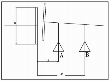
Adjust the pump’s leveling shims to roughly align the pump’s centerline, then tighten all leveling bolts (they must be tightened thoroughly, otherwise the measured data will be inaccurate);
Loosen all left and right leveling bolts, adjusting only the height, not the left and right.
Use a dial indicator to find the flat surface, and another to measure the outer diameter. Rotate the pump shaft and record the data. This allows you to calculate the coupling’s vertical opening K1, horizontal opening K2, vertical offset P1, and horizontal offset P2.
If it’s a vertical opening, then points A and B need to be raised.
The height point A needs to be raised is HA, and the height point B needs to be raised is HB. Therefore:
HA/L1=HB/L2=K1/D
So, HA=K1*L1/D HB=K1*L2/D
At the same time, the pump coupling is offset by P1, so points A and B should be lowered by P1 simultaneously. This means that the final upward heights of points A and B should be:
ha=K1*L1/D-P1 hb=K1*L2/D-P1
If hA and hB are positive, add shims of thickness hA and hB respectively; if negative, subtract shims of the corresponding thickness.
After adjusting the height, loosen the anchor bolts, adjust the left and right directions as described above, then tighten the anchor bolts. Use a dial indicator to check the center line to see if any correction is needed. Note that while tightening the anchor bolts, do not loosen the left and right top brackets.
After the center line is aligned, install the nylon connecting rod and check for any jamming. If there are no abnormalities, proceed with the operational test.
During the test, the bearing temperature may be slightly higher than normal. As long as it remains within the bearing’s operating temperature range and stabilizes without further increase, the test time can be extended slightly. The temperature will naturally decrease after the bearing has broken in. If the test proceeds without problems, the installation is successfully completed.
VI. Conclusion
Based on practical experience in repairing marine twin-screw pumps, this article provides a detailed description of the repair process for twin-screw pumps. It summarizes and organizes the key and challenging issues that need attention during repair, emphasizing some details that are often overlooked. The article offers valuable and replicable experience, hoping to be helpful in future twin-screw pump repairs.
